WHAT IS MIM
What Is MIM?
Complex Shapes. Precision Metal Parts.
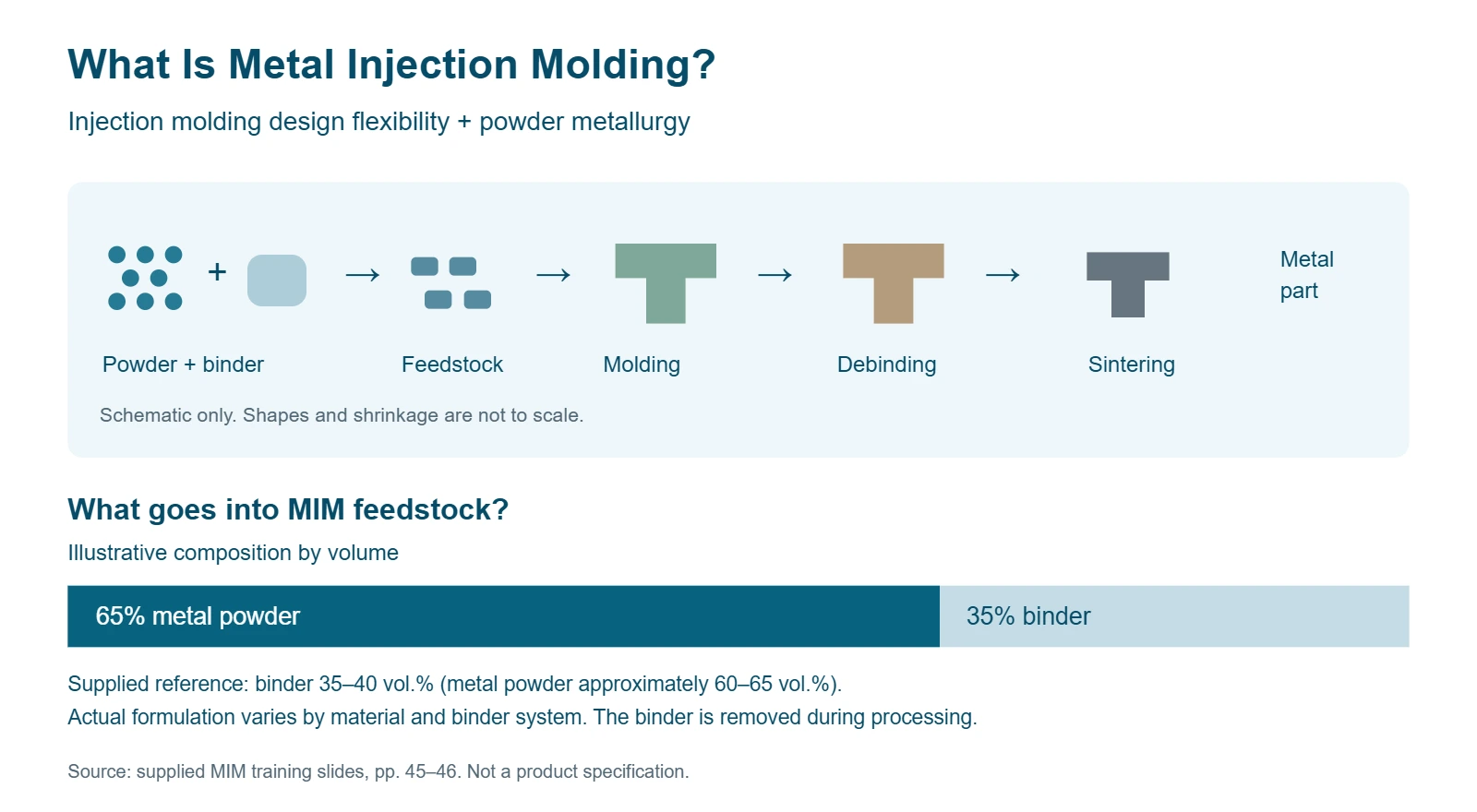
Metal Injection Molding (MIM) combines the shaping flexibility of plastic injection molding with powder metallurgy. Fine metal powder is mixed with a binder, molded into shape, then debound and sintered to produce a dense metal component.
MIM is particularly suited to small, complex metal parts produced in volume. It can combine multiple features in one component and reduce the need for machining.
Powder + binder
→
Feedstock
→
Molding
→
Debinding
→
Sintering
→
Metal part
Understanding the Feedstock
An illustrative feedstock contains 65% metal powder and 35% binder by volume. The binder enables molding and is removed during processing.
Composition varies by material and binder system. These figures are reference values, not product specifications.
How Does MIM Work?
From Metal Powder to Finished Parts
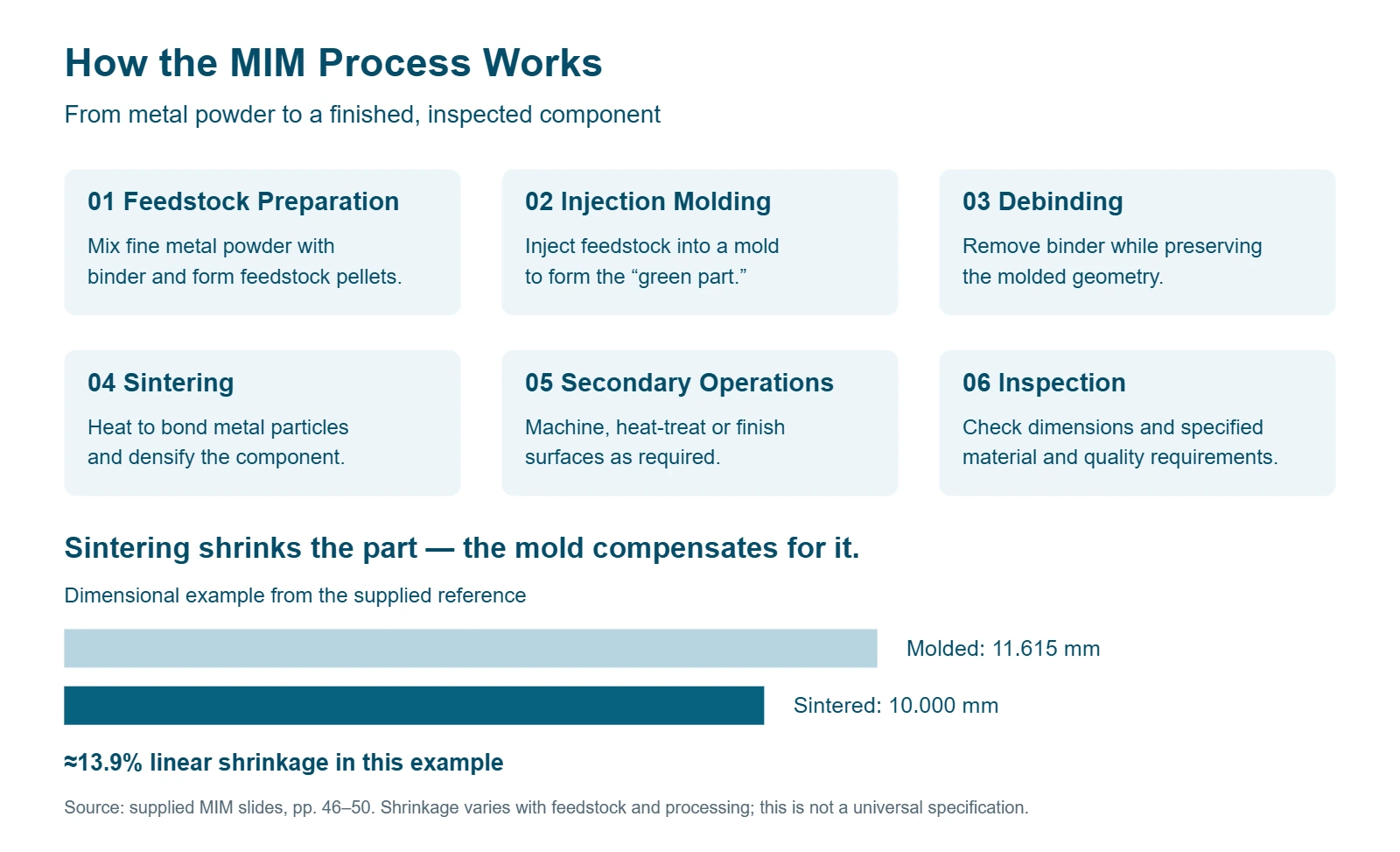
MIM transforms fine metal powder into complex metal components through molding, binder removal, and sintering. Secondary operations and inspection complete the process according to the part’s requirements.
1
Feedstock Preparation
Metal powder and binder are mixed and formed into pellets.
2
Injection Molding
Feedstock is injected into a mold to create a “green part.”
3
Debinding
Binder is removed while preserving the part’s shape.
4
Sintering
Controlled heating bonds the metal particles, increasing density and shrinking the part.
5
Secondary Operations
Machining, heat treatment, or surface finishing is applied as required.
6
Inspection
Dimensions and specified material and quality requirements are checked.
Why Is the Mold Larger Than the Finished Part?
Parts shrink during sintering, so the mold is designed to compensate. In the illustrated example, a molded dimension of 11.615 mm becomes 10.000 mm after sintering—approximately 13.9% linear shrinkage.
Actual shrinkage depends on the feedstock and processing conditions. This example is not a universal specification.
≈ 13.9% linear shrinkage
Key Features of MIM
Complex Geometry. Efficient Production.
MIM produces intricate metal components close to their final shape, combining design flexibility with efficient volume production.
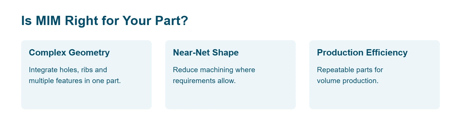
Complex shapes
Integrate holes, ribs, and multiple features into one component.
Less machining
Near-net-shape production can reduce material removal and finishing operations.
Material options
Suitable grades include stainless steels, low-alloy steels, tool steels, and selected specialty alloys.
Mechanical performance
Controlled sintering produces dense components, with properties determined by the alloy and processing conditions.
Repeatable production
Molding supports consistent geometry across production batches.
When Is MIM a Better Choice?
Best Suited to Small, Complex Parts Produced in Volume
MIM is worth evaluating when your part combines complex geometry, a suitable material, and sufficient production volume to justify tooling.
A Strong Candidate
Potential Benefit
Small parts with intricate features
Produce geometry that would require extensive machining.
Assemblies that can become one component
Reduce assembly steps and part count.
Difficult-to-machine alloys
Reduce cutting operations and material waste.
Recurring production demand
Spread tooling costs across more parts.
Compare total manufacturing cost—not just material price. Include tooling, secondary operations, inspection, and assembly when evaluating MIM.
Parts below approximately 30 g are common candidates in the supplied reference. This is a guideline, not a maximum weight limit.

What Should You Consider When Designing for MIM?
Design for MIM from the Start
Early engineering review helps control defects, cost, and lead time. Focus on these essentials:
Wall thickness: Keep sections as uniform as practical and avoid unnecessary bulk.
Mold release: Consider draft, undercuts, and how the part will be ejected.
Corners and support: Use suitable radii and support features to reduce stress concentration and distortion.
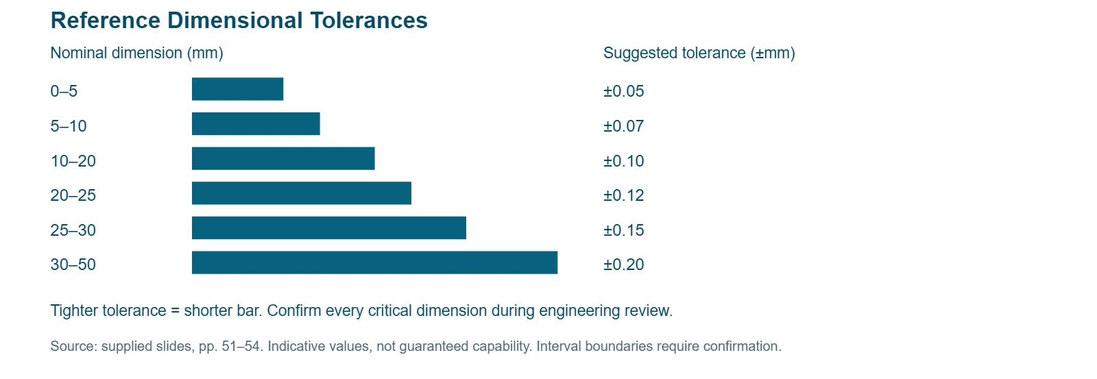
Critical dimensions: Identify functional surfaces and tight tolerances; secondary machining may be required.
Surface appearance: Agree on acceptable gate marks, ejector marks, and parting lines.
Material and quality: Define the alloy, required properties, surface finish, and inspection criteria before tooling.
Have a Part in Mind?
Send your drawing, material requirements, and expected annual volume for a MIM feasibility review.