 Skip to content
A typical RFQ goes like this: a buyer sends a 12 g 17-4PH latch, a CNC quote of $6.80 per piece, and one question: why does the MIM quote open with a $28,000 tooling line when the piece price is only $1.40?
Both numbers are right. They answer different questions. The CNC quote prices metal removal, part by part. The MIM quote prices a process that is expensive to set up and cheap to repeat: a hardened steel mold, a feedstock with roughly 40% binder by volume, a debinding step, and a sintering run in which every part shrinks about 15% to 20% linearly and has to land back inside drawing tolerance.
If you only compare piece prices, MIM looks cheap and you get surprised by tooling. If you only look at the tooling line, MIM looks expensive and you miss a part it was made for. The useful comparison is total cost at your real annual volume, with yield included. The rest of this article breaks the quote into the lines that move it, shows where the breakeven against CNC and investment casting usually falls, and lists what to send and ask before a first article gets cut.
Six lines that make up a MIM quote
Most of a MIM piece price is set before the first shot: by part mass, cavity count, furnace loading, and how many parts survive sintering in tolerance. The table shows how the lines usually split for a small stainless part at 50,000 to 100,000 pieces a year. Shares shift a lot with geometry, so read them as ranges, not a formula.
| Cost line | Typical share of piece price | What drives it | What you control |
|---|---|---|---|
| Tooling (amortized) | Paid up front, often 5%–15% when spread over year one | Cavity count, slides and lifters, core pins, steel grade | Undercuts, side holes, parting line, tolerance on molded features |
| Feedstock | 20%–40% | Alloy, powder type (gas- vs water-atomized), part mass plus runner | Wall thickness, coring, alloy choice |
| Molding | 10%–20% | Cycle time, cavities per shot, scrap and regrind rules | Thick sections that slow the cycle |
| Debind and sinter | 15%–25% | Parts per tray, furnace run length, atmosphere (H2, vacuum, Ar partial pressure) | Flat datums for setting, part height, self-supporting shape |
| Secondary operations | 0%–30% | Machining, coining, tapping, heat treatment, passivation, plating, polishing | Which features you ask to be “as-sintered” |
| Yield and inspection | Hidden in every line above | Scrap after sintering, sorting, CMM sampling plan | Realistic tolerances, clear critical-to-function dimensions |
Tooling: you pay for the steel once and for complexity every shot
A single-cavity tool for a simple part may start in the high four figures in USD. A four- or eight-cavity tool with slides and hot-runner tips can pass $30,000 to $60,000. The tool has to be cut oversize by the shrink factor, usually 1.16 to 1.22 for common feedstocks, and the first trial nearly always needs a steel adjustment round. Budget for one.
Cavity count is the main trade-off. More cavities cut molding cost per part but raise tooling cost and widen cavity-to-cavity variation, which shows up later as Cpk problems. For parts under roughly 30,000 pieces a year, a one- or two-cavity tool is often the cheaper program overall.
Where the tool is built matters as much as how. When the toolroom sits inside the molding plant, as ours does, there is no outside mold-shop margin, and a steel adjustment after T1 is a same-week job instead of a shipment back to a vendor. For NPI, a single-cavity prototype tool in pre-hardened steel takes 4 to 5 weeks to build and puts sintered samples in hand 10 to 15 working days after that. The production-tool lead time is confirmed with you once the samples are approved, because it depends on cavity count and the final design; changes to structure or dimensions after approval move that date. The trade-off is life: a prototype tool is good for a few thousand to a few tens of thousands of shots, has no slides beyond what the geometry forces, and gives shrink data that you then carry into the production tool. Use it to freeze the design, not to run volume.
Feedstock: you pay for every gram, including the runner
MIM feedstock costs several times more per kilogram than press-and-sinter PM powder, because it uses fine powders, typically D50 under about 20 µm, already compounded with binder. A 316L or 17-4PH part therefore carries a material cost that scales almost linearly with mass. This is why MIM is strongest below about 50 g and weakens past 100 g. Runner regrind can be reused within limits, but medical and aerospace customers often cap or forbid it, and that raises material cost.
Sintering: furnace loading is a price driver nobody sees on the drawing
Batch furnace cost is close to fixed per run. A part that sits flat, stacks on ceramic setters, and needs no custom support can be loaded densely. A tall, thin part that has to be propped on a V-groove setter to stop sagging can cut parts per run by half. Ask early how your part will be set; it changes the price more than most buyers expect.
Secondary operations: where a cheap net-shape part turns into a machined part
As-sintered MIM holds about ±0.3% to ±0.5% of nominal. A 20 mm feature at ±0.5% is ±0.10 mm. Ask for ±0.02 mm on that feature and you have bought a machining or coining step, a fixture, and a second inspection. That one callout can add 20% or more to piece price. Surface works the same way. As-sintered MIM surfaces typically come out around Ra 1.6 to 3.2 µm. That is fine for internal mechanisms, but a cosmetic face specified at Ra 0.4 µm means polishing labor on every piece. Heat treatment of 17-4PH (H900, H1025, H1150), passivation of 316L, and PVD or plating all add their own lines.
Yield: the line that sets the price you actually pay
Scrap after sintering is the most expensive scrap in the process, because the part already carries tooling, feedstock, molding, and furnace time. Uneven wall thickness, sharp internal corners, and long unsupported spans drive cracking and distortion. A part that runs at 85% yield instead of 92% carries about 8% more cost in every unit shipped, before sorting labor.
This is why yield should be written into the quote, not assumed. Yield depends on the part. A very simple part needs little work after sintering, while a part with features needs sizing and other secondary operations before it ships. We state the yield assumption in the quote after a DFM review of the drawing. When a feature puts that assumption at risk, we would rather flag it before tooling than absorb it later as scrap or pass it on as a price increase.
Breakeven: MIM vs CNC, investment casting and press-and-sinter PM
For the 12 g latch in the opening, MIM becomes the cheapest route at roughly 5,000 parts against CNC and about 7,000 against investment casting with finish machining. Below those quantities the tooling has not paid back.
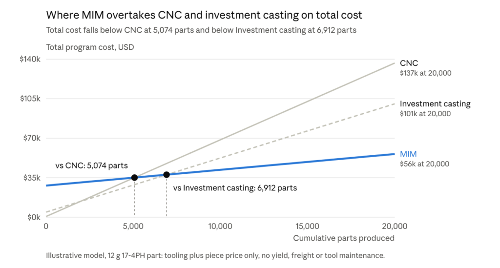
The model is deliberately simple: tooling plus piece price, straight lines. Real programs bend the lines in three ways.
- Yield moves the MIM line. The slope assumes parts ship at quoted yield. A part with a lower yield, for example 85% instead of 92%, steepens the MIM line and pushes the crossover out.
- Complexity moves the CNC line. CNC piece price rises fast with setups, small internal features, and hard alloys. Parts with cross holes, internal threads, or 17-4PH at H900 hardness often break even below 2,000 pieces. A simple turned pin may never break even.
- Program life moves everything. Tooling is a one-time cost. Over a three-year program, the volume that matters is lifetime volume, not one year’s.
Investment casting is the usual alternative above about 50 g, or when volumes are low and tolerances loose. Cast surfaces and tolerances (often ±0.5% to ±1% before machining) mean most precision features get machined. That machining is where its piece price sits.
Press-and-sinter powder metallurgy beats MIM on price for prismatic parts that can be pressed in one axis: gears, bushings, cams, and flanges. Its limits are geometry and density. Conventional PM parts sit around 6.6 to 7.2 g/cm³ for iron-based grades, below the 7.5 g/cm³ or more that a 17-4PH MIM part reaches at 96% to 98% relative density. If your part has undercuts, cross holes, or thin features off the press axis, PM is out and MIM is the comparison that matters.
Four DFM tweaks that take cost out of the piece price
On a part first drawn for machining or casting, four changes carry most of the savings. Together they can take a meaningful share out of the piece price. How much each one contributes depends on the part, so treat the ranges below as what we usually see, not a promise.
| DFM tweak | Cost lines it hits | Typical effect |
|---|---|---|
| 1. Core out and even out walls | Feedstock, molding cycle, debind time, yield | 10%–30% less mass; fewer distortion rejects |
| 2. Tight tolerances only where function needs them | Secondary operations, inspection | One machining or coining step removed per relaxed feature |
| 3. Design the part to sit in the furnace | Debind and sinter, yield | More parts per run; no custom setters |
| 4. Remove side actions and long core pins | Tooling, molding cycle, yield | Fewer slides; holes on position without machining |
1. Core out and even out the walls
Every gram is feedstock, and a thick section also cools slowly, debinds slowly, and shrinks differently from the thin wall next to it. Keep nominal walls between 1 and 6 mm and as uniform as the function allows. Keep adjacent sections within about 1.5:1, with generous transitions. A solid boss drawn only for stiffness can usually be cored and ribbed; that alone often takes 20% to 40% of the mass out of that feature.
The trade-off is stiffness and flow. Ribs thinner than about 0.5 mm are hard to fill, and coring too aggressively can leave knit lines where two flow fronts meet. We check fill and knit-line position against the gate before suggesting a core.
2. Put tight tolerances only where the function needs them
As-sintered MIM holds about ±0.3% to ±0.5% of nominal because every part shrinks 15% to 20% linearly, and that shrink varies a little with powder lot, molding density, and position in the furnace. Mark the critical-to-function dimensions on the drawing. Let everything else follow ±0.5% or ISO 2768-m, whichever is looser. Each feature pulled tighter than about ±0.3% is a candidate for machining, coining, or reaming, with its own fixture and inspection.
3. Design the part to sit in the furnace
At sintering temperature, roughly 1,300 to 1,380 °C for 316L and 17-4PH, the part is soft enough to sag under its own weight. Long unsupported spans and overhangs droop, and tall thin walls lean. There are two fixes. The tool can be biased so the part sags into shape, or the part can sit on a custom ceramic support. Both cost money and both add variation. The cheaper answer is a flat face parallel to the parting line that sits on a standard setter, with no overhang that has to hold itself up. That also lets more parts load per run, which is where furnace cost per piece is decided.
4. Remove side actions and long core pins
Every undercut that needs a slide adds tooling cost, cycle time, and a maintenance point. A side hole that can move to the pull direction, or be drilled in a quick secondary step, is often cheaper over the program. Core pins longer than about 2 to 3 times their diameter deflect under injection pressure, so blind holes end up off position and need machining anyway. Shorten them, or open the hole through.
Also check
- Internal corner radii of at least 0.3 mm. Sharp corners crack during debinding and sintering and wear the tool.
- The alloy against the job. 316L costs less to process for corrosion parts with light loads. 17-4PH reaches about 1,000 MPa or more after H900, at the cost of a heat-treat step. Fe-Ni low-alloy grades such as FN08 are cheaper again where plating handles corrosion. Specify against MPIF Standard 35 (MIM edition) or ASTM B883 so every supplier prices the same material.
- Part consolidation, with care. Merging three parts into one removes assembly, but a tall, uneven merged part can raise scrap faster than it saves labor.
- Density and dimensions are not tuned separately. Firing hotter to push density up also widens shrink scatter and, in 316L, raises the risk of delta ferrite and magnetism. Agree on the property you need and let the process be set around it.
Where yield is lost, and how to keep it
A cost-down that hurts sintered yield is not a cost-down. The defects below are the ones that most often decide whether a program yields well or badly, and each one starts earlier in the process than where it shows up.
| Defect at inspection | Where it actually starts | Countermeasure |
|---|---|---|
| Cracks after debinding | Thick-to-thin transitions, sharp corners, heating too fast in thermal debind | Even walls, radii ≥ 0.3 mm, debind ramp matched to the thickest section |
| Sag, warp, leaning walls | Unsupported spans at sintering temperature, uneven wall thickness | Flat setting face, tool bias for known sag, supports only where unavoidable |
| Dimensions drifting lot to lot | Powder lot variation, molding density, furnace position | Fixed feedstock lot per order, part weight monitored at molding, loading map per tray |
| Internal voids, low density in one zone | Gate on a thin wall causing jetting, short pack time, gate freezing early | Gate into the thickest section, pack time set from gate-freeze data |
| Grey surface, low corrosion resistance, magnetism in 316L | Residual carbon from incomplete debind, dew point too high, sintering temperature too high | Debind weight-loss check, atmosphere and dew point control, verified furnace temperature |
| Knit lines, short shots | Two flow fronts meeting at a thin rib, blocked vents | Gate and core position reviewed in DFM, vent cleaning on a fixed schedule |
How shrink is compensated
The tool is cut oversize by the feedstock’s shrink factor, typically 1.16 to 1.22. In theory shrink is isotropic. In practice packing pressure and gate position make it differ slightly along and across the flow, and thick sections shrink a little more than thin ones. So no shrink factor is right the first time on every dimension. At T1 we measure every critical dimension per cavity, compare it with the CAD, and correct the steel. Designing the tool steel-safe on critical features, so the correction removes steel rather than adding it, is what keeps that loop to one round.
RFQ checklist: send this, ask this
Two MIM quotes for the same drawing can differ by 2x and both be honest, because each supplier assumed a different cavity count, tolerance strategy, or secondary-operation route. Sending the information below, and asking the questions under it, makes quotes comparable.
Send with the RFQ
- 3D model (STEP) and 2D drawing with critical-to-function dimensions marked
- Material and required properties: tensile, hardness, corrosion test (for example ASTM B117 salt spray, hours), magnetic requirement if any
- Annual volume, typical order size, and expected program life in years
- Surface requirement per face: as-sintered, bead blast, polish (Ra), plating or PVD
- Cosmetic faces and where gate marks, ejector marks, and parting lines are allowed
- Assembly context: mating parts, press fits, threads, and which features are load-bearing
- Approval route: PPAP level, FAI, material certificates, RoHS or REACH declarations
Ask the supplier
- How many cavities is the quote based on, and what is tool life in shots?
- What shrink factor and feedstock (brand, powder type) are assumed?
- Which dimensions do you expect to hold as-sintered, and which need a secondary operation?
- What density and properties will you guarantee, and to which standard (MPIF Standard 35, ASTM B883)?
- How will the part be set in the furnace, and does it need custom supports?
- What sintered yield is the price based on, and what happens to price if it is not reached?
- How many tool adjustment rounds are included before T1 samples are approved?
- Who owns the tool, and what are the terms if production moves?
- Lead time for tooling, T1 samples, and first production lot, separately
If a quote cannot answer the cavity, tolerance, and yield questions, it is a guess. A guess usually reprices after T1.
Before the tool is cut
Most cost overruns on MIM programs trace back to decisions made in the two weeks before tool kickoff. Settle these four with your supplier while changing them is still free.
- Freeze the critical dimensions. Agree which three to five dimensions define function and how they will be measured (CMM program, datum scheme, sample size). Everything else gets a general tolerance.
- Agree on the gate and parting line. Gate location decides flow, knit lines, and density distribution, and it leaves a vestige. Approve its position on a drawing, not after T1.
- Decide what “approved” means at T1. Define how many parts per cavity get measured, which properties get tested, and what Cpk you expect at what stage. A T1 that looks good on five parts can still yield poorly in production.
- Plan for one steel adjustment. Even with good shrink data, the first sintered parts will be off on some dimensions. A tool designed with steel-safe margins on critical features can be corrected by removing steel. A tool without them has to be welded.
If you are weighing MIM for a new part, or trying to take cost out of one already in production, send the STEP file with your annual volume and the three dimensions that matter most. Within 7 working days you get a free DFM review that marks the walls, tolerances, and features driving cost or yield risk, plus a tiered quote: prototype tool (4 to 5 weeks) and sintered samples (10 to 15 working days after the tool is ready), a pilot lot, and production pricing at your volume, with tooling, piece price, and secondary operations on separate lines. That makes it easy to compare against your current process, and to see at what volume MIM starts paying for itself.
Share a link to your STEP file and drawing through our quote request form, or email leo@lichengmim.com.
Related reading
- MIM vs. CNC vs. Investment Casting: An Unbiased Engineer's Selection Guide
- How Long Does MIM Sampling Really Take? A Realistic NPI Timeline and How to Shorten It
- Managing Shrinkage & Sintering Distortion: How We Achieve ±0.3% Tolerance in Complex Geometries
- The Complete MIM RFQ Checklist: What Your Manufacturer Needs to Quote in 7 Working Days